Quality Core Tools
– APQP – FMEA – MSA – SPC – PPAP –
⇓ Introduction to Quality Core Tools
⇓ What are the Quality Core Tools

Introduction to Quality Core Tools
In the highly competitive environments of Automotive / Manufacturing, organizations are challenged with three simultaneous and equally momentous goals:
- Provide high quality products meeting or exceeding customer expectations
- Produce sustainable volume
- Deliver on time
To be successful in all three, the Quality Management System (QMS) standard IATF 16949 has evolved to provide guidance to these industries. The specific expectations of IATF 16949 are supported by the Quality Core Tools. When applied properly, the Quality Core Tools are the value-added methods and techniques that make it possible for an organization to achieve all three goals.
What are the Quality Core Tools
The Quality Core Tools are defined as five supplemental techniques and/or methods which support the expectations of IATF 16949. These tools are documented separately through the publication of five manuals available through Automotive Industry Action Group (AIAG). The traditional five core tools are listed in their order of use when designing products or processes:
- Advanced Product Quality Planning (APQP)
- Failure Mode and Effects Analysis (FMEA)
- Measurement Systems Analysis (MSA)
- Statistical Process Control (SPC)
- Product Part Approval Process (PPAP)
An additional core process included in Quality Core Tools discussions by Quality-One is:
- Special Characteristics
What is Advanced Product Quality Planning
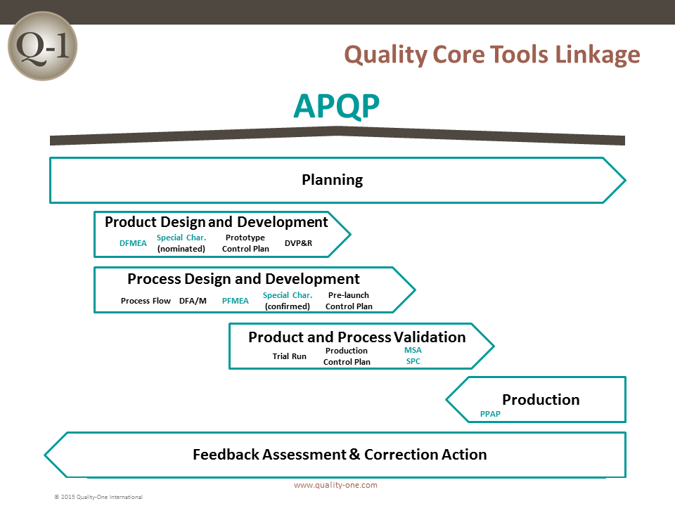
Advanced Product Quality Planning (APQP) is a tool box of methods and techniques which are used to assure product quality by communicating requirements, specifications and risks. APQP is a structured approach to product and process design which facilitates communication between suppliers, design communities and customers. APQP supports the never ending and relentless continuous improvement intent of IATF 16949. There are five sections or phases of APQP with an additional Input phase:
- Pre-Planning or Input
- The Pre-Planning phase supports investigation of lessons learned and the establishment of assumptions which are used to assure success.
- Plan and Define
- The reliability, quality and design goals are established, linking Voice of the Customer (VOC) to written and achievable requirements.
- Preliminary design concepts are used to establish a Bill of Material (BOM) facilitating Product and Process Planning.
- Product Design and Development
- The product design phase inserts reliability and quality tools into the project timeline intended to discover technical risks. Technical risk is the substitute for failure. Actions directed against identified risks are beneficial in preventing failure of products in both testing and use.
- Design Failure Mode and Effects Analysis (DFMEA) is one of many tools used in Section 2, which can identify risks for preventative action.
- Special Characteristics are refined and provided to the manufacturing and assembly activities, concurrently working in Section 3 Process Design and Development.
- Process Design and Development
- Manufacturing and assembly design is also a source for failure. Section 3 reveals risks, which if unchecked, could result in dissatisfied customers, late deliveries and production bottlenecks.
- Process Failure Mode and Effects Analysis (PFMEA) is one tool used in Section 3 to identify areas of risk requiring action prior to commitment to build tooling and equipment.
- All Special Characteristics are evaluated for prevention actions using Error Proofing, Statistical Stability / Capability or Mistake Proofing.
- Product and Process Validation
- The purpose of Section 4 is to produce evidence that the planning activities of Sections 1-3 were productive.
- Measurement Systems Analysis (MSA) is used to assure the evaluation and measurement system can determine product integrity.
- A first production trial run is used to determine quality through dimensional layout and use of Statistical Process Control (SPC). Special Controls and Control Methods are validated and documented in the Control Plan.
- The Production Part Approval Process (PPAP) documentation may be submitted for approval at the close of Section 4.
- Feedback Assessment and Corrective Action
- The product or service is now in full production. Lessons Learned captured from each phase are placed in a retrievable database for future reference.
- Experiences deemed beneficial are used to establish new levels of Standard Work and shared across the organization.
- Internal and External monitoring of performance for delivery, quality and continuous improvement (e.g. Risk Priority Number (RPN) reduction) follows the procedures required by IATF 16949.
- When failure is experienced, Root Cause Analysis (RCA) and Eight Disciplines of Problem Solving (8D) are utilized to find the root cause with the intent to correct it permanently.
What is Failure Mode and Effects Analysis (FMEA)
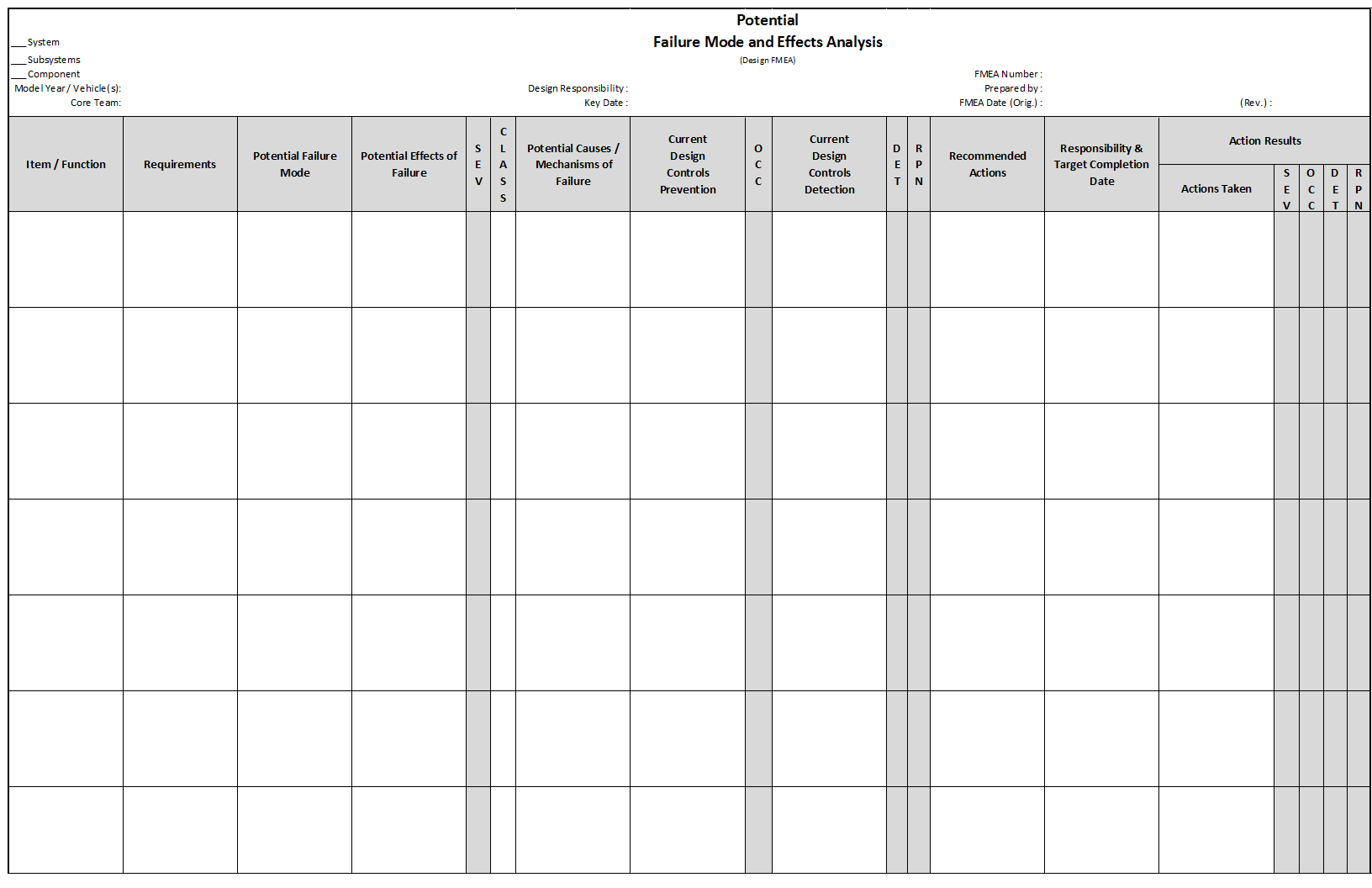
Failure Mode and Effects Analysis (FMEA) is a structured approach which identifies potential failure modes and resulting effects, coupling them with potential causes of failure. A technical risk level is assigned to each combination. When risk is deemed to be too great for the product or process being studied, actions are identified to mitigate the risk. FMEA also reviews the testing and evaluation techniques which can determine product design integrity and reliability (Design FMEA) or product quality (Process FMEA).
Evaluating risk and taking mitigating action is beneficial by preventing a failure before it is ever experienced. Several factors are utilized in the development of FMEA:
- Severity: Denotes how much danger or dissatisfaction exists for the failure and resulting effect
- Occurrence: Probability assessment of individual causes which have been linked to the failure mode
- Detection: Ranking of the effectiveness of catching either a design flaw prior to release of the design (DFMEA), or the ability of a process control at either preventing or detecting a defective condition which does not meet design intent (PFMEA)
- Risk Priority Number (RPN): The product of the three rankings for any one combination of potential failure/cause mechanism.
- An RPN threshold is not to be used to determine when to take an action
- Purpose of RPN is to assign an action and re-rank after action status is confirmed
- Setting arbitrary thresholds for RPN drives poor behavior of the team responsible for FMEA development
- Criticality: The combination of Severity and Occurrence, which may indicate an unacceptable risk
The use of FMEA permits other team members to review the work of the Design or Manufacturing / Process Engineer. Subject Matter Experts (SME) use their experience to judge the potential for failure at a time in the product / process development where changes can still be performed without much impact on program cost or timing.
What is Measurement Systems Analysis (MSA)
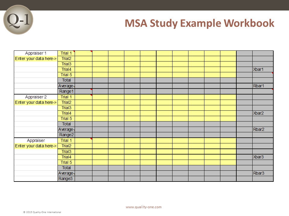
Measurement Systems Analysis (MSA) is an experimental process which determines the viability of an evaluation / measurement technique for use on a specific part characteristic. The need to make good quality decisions is the most important aspect of quality assurance and control. If the measurement system selected has too much variation or is unstable, an unacceptable product could be approved, resulting in customer dissatisfaction or worse. Conversely, acceptable product could be rejected, applying additional pressure on the organization to react to a condition that does not require action. Error in the measurement system is inevitable. Many assume that the measurement is absolute, which unfortunately is not true. Many times, the measurement system may be completely unacceptable and requires replacement or considerable improvement.
MSA looks at five distinct parameters:
- Bias: Most associated with calibration, bias is the amount of deviation of a measurement obtained from the system between a standard traceable to a standards organization (e.g. National Institute for Standards and Technology (NIST) or equivalent)
- Linearity: Refers to the difference of expected measurement bias over the range of the gage or device
- The device accuracy or bias does not remain the same throughout its useful measurement range
- Stability: The ability of a gage to provide the same measurement on the same product being measured over time
- The gage is not stable if it demonstrates a drift from previous measurements of the same part
- Repeatability: The measurement system is said to be repeatable if the same operator and gage, studied under the same conditions, can repeat the same result
- Poor repeatability would mean the operator uses the same part, measures it and obtains a different result from previous measurements (in identical conditions)
- Reproducibility: The system is considered reproducible if multiple operators can get the same or similar readings on the same parts
Guidelines for acceptance are based on two principles:
- Percent Error to Tolerance: The total variation of the blended repeatability and reproducibility divided into the total tolerance. This evaluation is used to validate a gage system initially.
- Percent Error to Variation: The total variation of the blended repeatability and reproducibility divided into the total variation of the product/process. This evaluation is used to determine if SPC can be reduced or eliminated when combined with high capability results (Cpk=1.33 or greater).
The guidelines for acceptance are as follows:
- 10% error or less preferred
- 10-30% error acceptable depending on factors such as cost to measure, severity of the effect of a failure or cost to repair the gage
- If greater than 30%, the gage system is unacceptable and requires improvement or replacement
What is Statistical Process Control (SPC)
Developed by Walter Shewhart at Bell Telephone, Statistical Process Control (SPC) is a collection of statistical techniques intended to understand the behavior of a system. SPC uses the primary statistical principles of Central Tendency (Mean, Median and Mode) and Variation (Spread or Standard Deviation). A process under study will reveal if it is operating in a stable and predictable way or in control.
The Normal Distribution
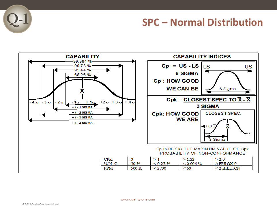
SPC is generally based upon the normal distribution. The Normal Distribution depicts a bell shape with known percentages in the area under the curve. The location of the curve (the central tendency) directly relates to the specification of the characteristic being measured. The spread of the curve is determined by adding 3 standard deviations (sometimes referred to as sigma) on each side of the central tendency. The percentage of product fitting under the curve can be applied to the process under study. For example:
- ± 1 sigma from the central tendency has 68.26%
- ± 2 sigma from the central tendency has 95.5%
- ± 3 sigma from the central tendency has 99.73%
If a process is running normally, its output will fit this percentage model. SPC utilizes the control chart to show the output “in real time”, shortening the reaction time if something does not agree with a previously proven process.
Control Charts
Control Charts are typically used to indicate patterns which may be different than the expected bell curve percentages. When a pattern is observed, the process is out of control and actions to investigate are common. Control Charts fall into two categories, variable and attribute. Variable Control Charts utilize data which, when plotted on the chart, can be interpreted. Attribute Control Charts show performance of a Go / No Go data set.
Variable control charts typically come in pairs; one for the central tendency and another for the spread. Each chart has a line drawn for the measurement of central tendency and control limits, equidistant lines on either side of the central tendency. The control limit lines equate to the expected spread at ±3 standard errors based on the sample size of the group or subgroup.
Samples are chosen at specified frequencies and the two points, one for central tendency, the other for spread, are plotted. The plotted points are evaluated along with up to six previous points. The stability of the process is determined through the following criteria:
- Point outside the control limit line
- 7 points in a row on either side of the central tendency lines
- 6 or 7 points in the same direction
- 7 points in a row that hug the central tendency
When this criterion is used, the chart can indicate what will likely come next. Out of control does not relate to bad product, just different from previous experience. A chart may indicate an out of control condition but upon close examination, the analyst may want to keep it that way and establish a new best case.
Attribute control charts only depict conditions which are unacceptable. Actions are performed to improve the undesirable state. Attribute control charts are often linked to continuous improvement because they can be excellent visual aids to show progress.
What is Production Part Approval Process (PPAP)
Production Part Approval Process (PPAP) is a standardized process in the automotive and aerospace industries. PPAP demonstrates through documentation that as manufactured, the product and process perform as specified by design intent and purchasing requirements. The elements of PPAP are related to APQP in that they are created at key times during product and process design. The evidence of conformance is collected and provided as validation of proper planning. PPAP promotes a clearer understanding of the requirements to manufacturers and suppliers. PPAP also helps to ensure that the processes selected to manufacture parts can consistently reproduce the parts at planned production volumes. For automotive industry suppliers, the PPAP process is currently governed by the PPAP manual published by the Automotive Industry Action Group (AIAG).
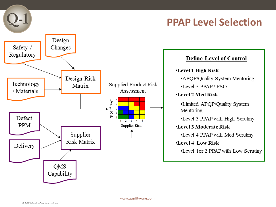
PPAP is deployed at five levels based on risk. The lowest risk levels are 1 and 2 and are reserved for simple designs and well respected suppliers / manufacturers. Level 3 is the default, which requires all applicable elements be provided. Level 4 is the customized selection, used when specific changes require closer examination. Level 5 is reserved for the greatest risk parts and suppliers. When level 5 is indicated, additional supplier-customer collaboration is required. Level 5 often results in customer visitation during key core tool development and possibly during the first production trial run. The PPAP submission is similar to sample submissions used in many industries, however PPAP documentation must include prevention tools in addition to those which show product and process conformance.
A Cross Functional Team (CFT) is needed to complete PPAP documentation, as there are elements requiring input from:
- Supplier Procurement and Subcontracts
- Design Engineering
- Process and Manufacturing Engineering
- Quality Assurance and Control
- Manufacturing Operations
- Laboratory Activities
Why Use Quality Core Tools
The Quality Core Tools are used during the Product and Process Development phases of New Product Introduction (NPI) and during certain events such as experienced failure or engineering changes. The Quality Core Tools methodology from Quality-One harmonizes and links the inputs and outputs of the core tools to one another. Unlike many who see the tools as independent, linked tools increases their value to one another and reduces overall workload.
The main goals for any project are:
- Provide high quality products meeting or exceeding customer expectations
- Produce sustainable volume
- Deliver on time
APQP and FMEA assure quality through prevention activities related to risk. APQP additionally supports on time delivery through planning and enhanced communication. Evidence of achieved quality is gathered by using superior gage systems validated through MSA and data collected and analyzed using SPC. Reviewing the Quality Core Tools, from inputs to outputs, an analyst would observe:
- APQP provides requirements, specifications, reliability / design goals, preliminary special characteristics, timing and guidance for all activities and tools, including the remaining Quality Core Tools, involved in product and process prevention and control
- Design FMEA Risk Assessment provides refined special characteristics, inputs to testing and design improvements
- Process FMEA Risk Assessment considers possible process weaknesses, improved process performance and control strategies on special characteristics
- MSA validates the gage systems used for measurements of special characteristics, which are critical for proper identification of product quality failures
- SPC demonstrates process stability and capability for special characteristics originally derived from DFMEA and PFMEA
- PPAP demonstrates that all special characteristics have achieved a level of acceptable stability and capability (Cpk) and / or development of special controls
The common thread that all Quality Core Tools share are the Special Characteristics. Each tool receives Special Characteristics and either refines them, treats them or eliminates the need for them. Progress is measured based on the number of risks discovered and mitigated prior to PPAP.
How to Apply Quality Core Tools
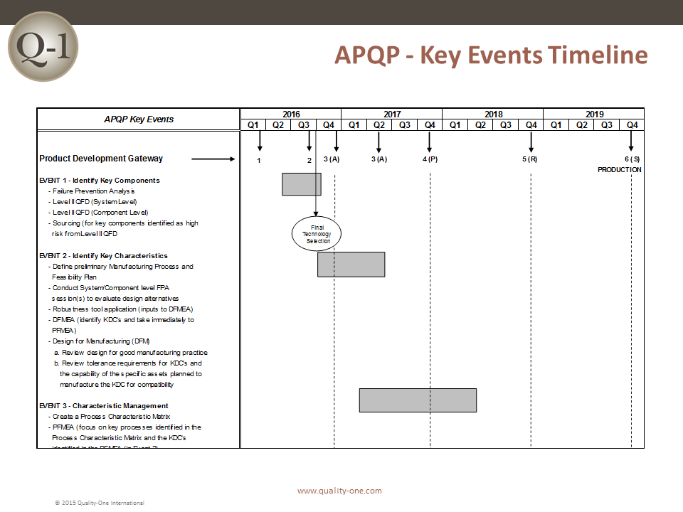
Quality Core Tools are applied sequentially and collaboratively. Collaborative Product Process Design (CPPD) depicts both a timing overlap of activities and a cross-functional communication between engineering communities.
Each Quality Core Tool’s output is linked to other tools in the Product Quality Plan. The timing for Quality Core Tools should be early product / process development as practical. Waiting until the last minute is not efficient and has low / no impact on quality. The creation of the paperwork to “check the box” has no redeeming benefit to an organization.
An example of the value-added linkage can be demonstrated using the DFMEA and PFMEA relationships:
- The design team will identify specific dimensions, material properties and tolerances, including the severity and effect on the customer. This is what is meant by a Special Characteristic. The type of characteristic is dependent on the DFMEA severity (Critical, Significant, High Impact, etc.)
- Special Characteristics are provided to the Manufacturing / Process Engineer well in advance of a finished design or drawing being available
- Timing for this transfer is critical; the transfer or collaboration must be as soon as possible
- Once received by the Manufacturing / Process engineer, the Special Characteristic is linked to a process technology from the process flow chart
- Special Characteristics are then transferred into the PFMEA as Failure Modes for the related Process Step(s)
- Risk analyzed of process failure resulting in the Special Characteristic being produced incorrectly
- Manufacturing / Process team will collaborate with the design team to discuss Design for Manufacturability or Design for Assembly (DFM/DFA)
- Control Plan is created with special controls to either error proof, mistake proof or detect the failure or cause
A more detailed application of the Quality Core Tools can be found by exploring the following links:
Learn More About Quality Core Tools
Quality-One offers Quality and Reliability Support for Product and Process Development through Consulting, Training and Project Support. Quality-One provides Knowledge, Guidance and Direction in Quality and Reliability activities, tailored to your unique wants, needs and desires. Let us help you Discover the Value of Quality Core Tools Consulting, Quality Core Tools Training or Quality Core Tools Project Support.

